Tuesday, October 16, 2012

Lack of time to start standby pump after duty pump failed

As per P&ID there are two pumps that were designed for duty and standby.


The auxiliary system was provided lubrication system with air cooler for each particular pump.


 There are lubricating pump motors, pressure switch, pressure transmitter and air cooler motor equipped in skid, the control and sequencing function by ICSS.
As per function is the auxiliary system running while main running (if main does not run then auxiliary system does not run as well).
As per function idea whenever the duty pump was failed but standby pump will not able started immediately because the sequencing function will go to start the lubrication pump, opening the solenoid valve and starting the air cooling fan and eventually start the main pump.
So there is some delay time between duty pump failed and standby pump run.     


Sunday, October 14, 2012

Junction Box (Stainless Type)

Junction box - Rain channel

The PLC junction box was supplied with booster compressor and also installed offshore, in the first day of offshore commissioning we found the raining water leaked into the control panel, and we found a lot of things need to change and repair.


As observation we found the rain channel very short and slope, also the rain in sea is heavy and undirection.


  I would recommend to provide the junction box that having rain channel more space and slope.


Saturday, October 13, 2012

Wellhead Platform

Remotely Wellhead Platform

The typically wellhead platform comprised:
1.       Xmas Trees

Xmas Tree cross section

Subsea safety valve
The Xmas trees hooked up to flowline.

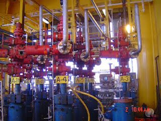
The wellhead panel and wellbay area.
Add caption
The wellbay area.
2.       Flow lines

Flowline hooked to Xmas Tree

3.       Choke valves


Choke valves drived by hydraulic oil

4.       Manifolds

The manifolds and lineed up automated valves

Lined up automated valves
5.       Test Separator
Test Separator

Test Separator

6.       Launcher

7.       Closed drain system

Closed drain tank

Closed drain pump
8.       Fuel gas system
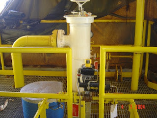
Fuel gas scrubber
9.       Chemical injection system

Chemical injection skid
10.   Compressor (booster or gas lift)
11.   Crane
12.   Wellhead panel

Wellhead panel

13.   Generator (gas and diesel, if required) or TEG
14.   Automation system
15.   Radio system
16.   Nav aids
17.   Chargers and batteries
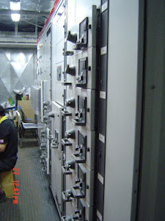
18.   Power distribution board

Monday, October 1, 2012

Air Compressors and Dryers (Modified Package)

The air compressors were modified to meet hazardous area requirments by packager, the electrical and instrument equipments were changed and adding some enclosures, glands and cables.


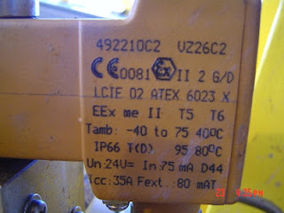
Unfortuntely there were solenoid valves of dryers were burnt, only coils changed and valve bodies existed, the coil energy does not enough to push and pull then heat up at coils and also DO of PLC were burnt.


The new solenoid valves were replaced, rewiring and adding interposing relays.


The customer must be carefully design review and testing to ensure the modifiled that works properly.

The brass pressure safety valves supplied from manufacture also obstructed so it must be cleaned and tested after mechanical completion. 


The process instrumentation were mounted on enclosure that is easily to vibration.


  By changing motor to comply the hazardous area then motor dimension required more room to install.


Sunday, September 30, 2012

ESP Pump


Vendor pump curve

LV MCC

Step up transformer (customer has only LV generators that are available)


Variable speed drive

MV cables


Terminated junction boxes to ESP vendor's cables


ESP connector


MV cables connected to X'Mas
ESD cables

ESP HMI (note: no subsea valve to connect to wellhead control panel, because it always opened prevent back pressure whe ESP pump trip 

ESP pump supplied by vendor

ESP pump


installed ESP to tubing


Installed ESP cable along tubing


Installed cable


Installed cable